From Norm on The Live-Aboard List:
There have been many requests for alternator information so here goes ...
First, understanding the beast.
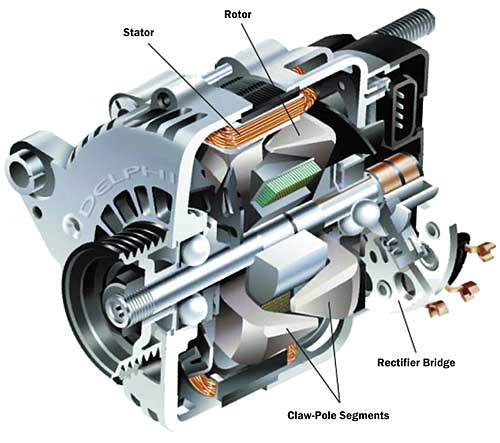
Electricity is made in an alternator by pushing and pulling electrons with a magnetic field. The magnetic field is created in "the rotor" by passing current through coils of wire in the rotor. The magnetic fields thus created, when rotated, sweep through a set of stationary coils, called collectively "the stator", pushing and pulling electrons as they pass by. The coils of both the rotor and the stator are wrapped around hunks of iron to concentrate and direct the magnetic fields.
The streams of electrons in the stator coils being pushed and pulled by the passing north/south magnetic poles are guided by electron check-valves, called "diodes" so that all the pushed electrons go to the negative terminal, (usually grounded but sometimes brought to a terminal labeled "E" for earth, "G" for ground, or "Neg" for negative), and all the pulled electrons make an electron "vacuum" at the positive terminal (usually a threaded stud marked "B" or "Bat" for battery).
The rotor gets its energizing electricity through slip rings and brushes. On the shaft, almost always on the end opposite the pulley, there are two round copper rings encircling the shaft. The wire coil of the stator begins and ends at these rings. Pressing against each slip ring is a carbon block (called a "brush"), sliding in a retaining metal and pushed against the slip ring by a spring. Each brush has a flexible stranded copper wire molded into it. One of these brushes is (usually) connected to ground, and the other to a voltage regulator, either built into the alternator or external to it.
If the regulator is external, the ungrounded wire is led to a connector blade or stud (usually) marked "F" for field. If the regulator is internal, this brush is connected to the internal regulator instead.
If the regulator is internal there is a connection marked "I" (for ignition) that has 12 VDC applied when the engine is running. When the engine is stopped the 12 VDC is removed to tell the regulator to stop sending field current to the rotor so it doesn't drain the battery when the engine is stopped.
What the regulator does is to vary the current going through the rotor in order to maintain the output voltage at the Battery terminal to a fixed value despite load changes as the battery charges up or you switch things off and on. For cars, this voltage is set to maintain a battery which is used very little. Starting an engine takes very little energy. It takes a great deal of power, but for a very short time, so it is really not much energy. Once the engine is started, the alternator powers all the loads and the battery is quickly refilled and trickle charged thereafter.
To charge deep cycle batteries, we charge them much much harder than an engine starting battery because they are mostly empty to start (which is what makes deep cycle batteries different, they have thick, strong, plates that can take this kind of power), very different from an engine starting battery which is almost fully charged all the time. This is why we need to get control of the current going through the rotor, the "field current", so we have the say-so about how strongly the alternator pushes electrons through the battery.
(Years ago the magnetic field was stationary, creating a "field" of magnetic force that rotating coils were spun in to create the electricity, the opposite of the way we do it today. The rotating part had segmented slip rings that only allowed current to flow through the brushes and to the battery when the rotating coil was in position to supply only positive juice to one brush and only negative polarity to the other. Since diodes take care of that now, we don't need that segmented slip rings (called a commutator) to do it.)
I presume that the bearings are OK. If the rotor moves easily and smoothly the bearings are probably OK. If this is not the case, then you are probably better off trading the unit in for fresh one unless it is a big, expensive unit, in which case a machine shop can help you change the bearings.
Now, let's take the alternator apart.
First, clean the alternator if it is cruddy. I use Gunk (spray-on engine cleaner), a parts cleaning brush (round, stiff) and water. Fresh water will not harm the alternator.
If the pulley comes off easily, remove it. If it does not, don't worry, it may not be necessary to remove it, but it would make things easier if it is off because you then can separate the pulley side of the case from the rotor.
The case is (usually) in three pieces - Pulley half (usually cast aluminum), stator (usually a bundle of flat iron stampings about 1/16" thick) and the rear half (usually another aluminum casting much like the pulley half). This sandwich is (usually) held together with two, three or four long machine screws located around the perimeter of the unit.
Take a punch or something and make marks on the three parts of the case (called "witness marks") so you can put it back in exactly the way it was. This may not be necessary - it may only go back one way - but it is good practice. Someday you will be glad you did, usually after you wished you had.
Remove these screws and remove the rear half of the shell. You may need a screwdriver/chisel and hammer to break them apart. Use the biggest hammer you have and strike gently. You may need to unscrew nuts holding terminal studs. Work carefully. Avoid breaking anything. If something doesn't go the way you think it should, look very carefully to see what the hang-up is. Sometimes it's just friction, sometimes not. Unfortunately, it is a fact of engineering that most of us learn how hard to push by breaking things. This is the only way to get "Experience".
If all goes well, the rear housing will come off and you will see all the above-mentioned parts inside. If the laminated strata, the stator, wants to stay stuck to the rear housing, let it, and remove them both. The wires from the coils of the stator will be securely attached to the diode assembly (called a "diode pack"), usually soldered, so the diode pack and the stator will stay together. Separate the three parts of the case if you can. The pulley half, the stator (with diode pack attached) and the rear half of the case.
Identify: Rotor - it's the part that spins, stator - a circle of coils wrapped around laminated iron poles, will have the diode pack attached, internal regulator (if present) - it will look like an irregular hunk of plastic with bits of metal coming out of it.
The slip rings on the rotor shaft will be (usually) pretty, polished and coppery. The brushes will be protruding way out of their retainers (their guides) and may even be flopping around loose on their wires. With the case together they only have a little bit sticking out because they are up against the slip rings.
The diode pack will be a complex array of diodes attached to the stator. Individual diodes will be about 3/8" in diameter pressed into some sort of metal plate with a stiff wire sticking up from each of them. The stud for the "B" (battery) connection may be attached to the diode pack.
The regulator (if present) will have connections to ground (or "E"), one of the brushes, the 12 VDC output, and the connection "I". There may also be a connection for the dashboard "idiot light" and/or a connection to pick up the pre-rectified AC to provide a RPM-proportional signal for an electronic tachometer.
To convert an internally regulated alternator [to externally regulated], we must identify the brush that goes to ground, and the brush that goes to the internal regulator. You then sever the connection between the regulator and the brush and attach a new wire to the brush leading the wire through a vent passage to outside of the case. I usually crimp a 1/4" blade type connector here to connect the external regulator.
Severing the internal regulator connection often means cutting a piece of metal. I have used a cutoff wheel in a Dremel tool most often. Cut enough of a gap so that it will never arc. Then "tin" the metal part that you want to attach your new field wire to by scraping the surface shiny clean and wetting with a nice little blob of solder. You can use acid core solder here if regular rosin core solder has a problem but you must wash off the excess acid flux with a toothbrush and water. Tin the wire too, but only with rosin core (acid flux will wick up into the wire and cause it to break later on). Solder the two parts together. This part of the operation allows you to show off your skill with soldering, stress relief for the field wire, etc.
Sometimes it will be possible to use an already in place connector, such as the now useless "I" or idiot light connection, but you must isolate it from its former connection. Perhaps use a small machine screw with shoulder insulating washers to create a new insulated stud on the case.
Putting the unit back together is straightforward except for the brushes. You usually have to hold them back away from the slip rings somehow when you mate the rotor and rear case back together. I worked on one unit that some wonderful designer had provided little holes in the case and brush retainer so I could simply slip two little pieces of wire in there to hold back the brushes. After assembling the case, I just removed the two wires! But more often I use fishing monofilament to hold back the brushes, then cut the lines and withdraw them from the case after everything was back together. I always use anti-seize on any threaded fasteners when re-assembling machines.
If you want, take it down to the auto parts shop and have them test it on their test stand. Be careful not to strain the field wire. Maybe you could put a little ty-wrap somewhere to anchor it.
First, understanding the beast.
Electricity is made in an alternator by pushing and pulling electrons with a magnetic field. The magnetic field is created in "the rotor" by passing current through coils of wire in the rotor. The magnetic fields thus created, when rotated, sweep through a set of stationary coils, called collectively "the stator", pushing and pulling electrons as they pass by. The coils of both the rotor and the stator are wrapped around hunks of iron to concentrate and direct the magnetic fields.
The streams of electrons in the stator coils being pushed and pulled by the passing north/south magnetic poles are guided by electron check-valves, called "diodes" so that all the pushed electrons go to the negative terminal, (usually grounded but sometimes brought to a terminal labeled "E" for earth, "G" for ground, or "Neg" for negative), and all the pulled electrons make an electron "vacuum" at the positive terminal (usually a threaded stud marked "B" or "Bat" for battery).
The rotor gets its energizing electricity through slip rings and brushes. On the shaft, almost always on the end opposite the pulley, there are two round copper rings encircling the shaft. The wire coil of the stator begins and ends at these rings. Pressing against each slip ring is a carbon block (called a "brush"), sliding in a retaining metal and pushed against the slip ring by a spring. Each brush has a flexible stranded copper wire molded into it. One of these brushes is (usually) connected to ground, and the other to a voltage regulator, either built into the alternator or external to it.
If the regulator is external, the ungrounded wire is led to a connector blade or stud (usually) marked "F" for field. If the regulator is internal, this brush is connected to the internal regulator instead.
If the regulator is internal there is a connection marked "I" (for ignition) that has 12 VDC applied when the engine is running. When the engine is stopped the 12 VDC is removed to tell the regulator to stop sending field current to the rotor so it doesn't drain the battery when the engine is stopped.
What the regulator does is to vary the current going through the rotor in order to maintain the output voltage at the Battery terminal to a fixed value despite load changes as the battery charges up or you switch things off and on. For cars, this voltage is set to maintain a battery which is used very little. Starting an engine takes very little energy. It takes a great deal of power, but for a very short time, so it is really not much energy. Once the engine is started, the alternator powers all the loads and the battery is quickly refilled and trickle charged thereafter.
To charge deep cycle batteries, we charge them much much harder than an engine starting battery because they are mostly empty to start (which is what makes deep cycle batteries different, they have thick, strong, plates that can take this kind of power), very different from an engine starting battery which is almost fully charged all the time. This is why we need to get control of the current going through the rotor, the "field current", so we have the say-so about how strongly the alternator pushes electrons through the battery.
(Years ago the magnetic field was stationary, creating a "field" of magnetic force that rotating coils were spun in to create the electricity, the opposite of the way we do it today. The rotating part had segmented slip rings that only allowed current to flow through the brushes and to the battery when the rotating coil was in position to supply only positive juice to one brush and only negative polarity to the other. Since diodes take care of that now, we don't need that segmented slip rings (called a commutator) to do it.)
I presume that the bearings are OK. If the rotor moves easily and smoothly the bearings are probably OK. If this is not the case, then you are probably better off trading the unit in for fresh one unless it is a big, expensive unit, in which case a machine shop can help you change the bearings.
Now, let's take the alternator apart.
First, clean the alternator if it is cruddy. I use Gunk (spray-on engine cleaner), a parts cleaning brush (round, stiff) and water. Fresh water will not harm the alternator.
If the pulley comes off easily, remove it. If it does not, don't worry, it may not be necessary to remove it, but it would make things easier if it is off because you then can separate the pulley side of the case from the rotor.
The case is (usually) in three pieces - Pulley half (usually cast aluminum), stator (usually a bundle of flat iron stampings about 1/16" thick) and the rear half (usually another aluminum casting much like the pulley half). This sandwich is (usually) held together with two, three or four long machine screws located around the perimeter of the unit.
Take a punch or something and make marks on the three parts of the case (called "witness marks") so you can put it back in exactly the way it was. This may not be necessary - it may only go back one way - but it is good practice. Someday you will be glad you did, usually after you wished you had.
Remove these screws and remove the rear half of the shell. You may need a screwdriver/chisel and hammer to break them apart. Use the biggest hammer you have and strike gently. You may need to unscrew nuts holding terminal studs. Work carefully. Avoid breaking anything. If something doesn't go the way you think it should, look very carefully to see what the hang-up is. Sometimes it's just friction, sometimes not. Unfortunately, it is a fact of engineering that most of us learn how hard to push by breaking things. This is the only way to get "Experience".
If all goes well, the rear housing will come off and you will see all the above-mentioned parts inside. If the laminated strata, the stator, wants to stay stuck to the rear housing, let it, and remove them both. The wires from the coils of the stator will be securely attached to the diode assembly (called a "diode pack"), usually soldered, so the diode pack and the stator will stay together. Separate the three parts of the case if you can. The pulley half, the stator (with diode pack attached) and the rear half of the case.
Identify: Rotor - it's the part that spins, stator - a circle of coils wrapped around laminated iron poles, will have the diode pack attached, internal regulator (if present) - it will look like an irregular hunk of plastic with bits of metal coming out of it.
The slip rings on the rotor shaft will be (usually) pretty, polished and coppery. The brushes will be protruding way out of their retainers (their guides) and may even be flopping around loose on their wires. With the case together they only have a little bit sticking out because they are up against the slip rings.
The diode pack will be a complex array of diodes attached to the stator. Individual diodes will be about 3/8" in diameter pressed into some sort of metal plate with a stiff wire sticking up from each of them. The stud for the "B" (battery) connection may be attached to the diode pack.
The regulator (if present) will have connections to ground (or "E"), one of the brushes, the 12 VDC output, and the connection "I". There may also be a connection for the dashboard "idiot light" and/or a connection to pick up the pre-rectified AC to provide a RPM-proportional signal for an electronic tachometer.
To convert an internally regulated alternator [to externally regulated], we must identify the brush that goes to ground, and the brush that goes to the internal regulator. You then sever the connection between the regulator and the brush and attach a new wire to the brush leading the wire through a vent passage to outside of the case. I usually crimp a 1/4" blade type connector here to connect the external regulator.
Severing the internal regulator connection often means cutting a piece of metal. I have used a cutoff wheel in a Dremel tool most often. Cut enough of a gap so that it will never arc. Then "tin" the metal part that you want to attach your new field wire to by scraping the surface shiny clean and wetting with a nice little blob of solder. You can use acid core solder here if regular rosin core solder has a problem but you must wash off the excess acid flux with a toothbrush and water. Tin the wire too, but only with rosin core (acid flux will wick up into the wire and cause it to break later on). Solder the two parts together. This part of the operation allows you to show off your skill with soldering, stress relief for the field wire, etc.
Sometimes it will be possible to use an already in place connector, such as the now useless "I" or idiot light connection, but you must isolate it from its former connection. Perhaps use a small machine screw with shoulder insulating washers to create a new insulated stud on the case.
Putting the unit back together is straightforward except for the brushes. You usually have to hold them back away from the slip rings somehow when you mate the rotor and rear case back together. I worked on one unit that some wonderful designer had provided little holes in the case and brush retainer so I could simply slip two little pieces of wire in there to hold back the brushes. After assembling the case, I just removed the two wires! But more often I use fishing monofilament to hold back the brushes, then cut the lines and withdraw them from the case after everything was back together. I always use anti-seize on any threaded fasteners when re-assembling machines.
If you want, take it down to the auto parts shop and have them test it on their test stand. Be careful not to strain the field wire. Maybe you could put a little ty-wrap somewhere to anchor it.
From "Secondary Engine Loads" article by Don Casey in Nov/Dec 2001 issue of Blue Water Sailing magazine:
- When sizing an alternator, use the hot rating, not
the (advertised) cold rating. Hot usually 25% less than cold.
- Bigger alternator requires bigger belt.
- Dual pulleys allow more pull, but put it
further out on end of crankshaft (bad).
- Put new alternator on new bracket: can keep old alternator as spare,
size new bracket properly, and have new alternator oppose old on shaft.
- Every 25 amps of 12-volt alternator output will consume about one horsepower.
- Good to have regulator that avoids loading engine until a minute or two after it starts.
See Alternator section of my DC Electricity Generation on a Boat page